Automatic Sliding Gate Opener System

Technical Parameters of Automatic Sliding Gate Opener

Model

SL1500AC

Power Supply

220V/50Hz;110V/60HZ

Motor Power

550W

Gate Moving Speed

11-13M/Min

Maximum Weight of Gate

1500Kg

Remote Control Distance

30M

Remote Control Mode

Single Button Mode / Three Button Mode

Limit Switch

Spring Limit Switch / Magnetic Limit Switch

Noise

<60dB

Working Duty

S2, 20 Min

Recording of Remote Controls

25

Frequency

433.92 MHz

Working Temperature

-20 Degree to 70 Degree Celsius

Automatic sliding gate Installation:

  • SL1500AC Sliding gate Opener is applicable to gate weight less than 1500Kg, and length of the sliding gate less than 12 Meter or 38 Feet. The drive mode adopts the rack and gear transmission. This gate opener must be installed inside the enclosure or yard for protection.

Main engine installation of Heavy duty sliding gate Motor:

  • Dismantle the plastic housing on the main engine before installation and keep the relevant Fasteners properly.
  • Please prepare the power line for connecting the mounting plate to the main engine (the number OT power Supply cable cores should not be less than 3 PCS, the sectional area of cable core should not be less than 3 PCS, the sectional area of cable core should be over 1.5mm Square and the length should be determined by users according to the situation on installation spot).
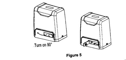
  • Please unlock the main engine before installation, the unlock method is: remove the rubber key cover, insert the key and open the manual release bar till t rotates by 90 Degree as shown in bellow Figure 5 . Then tum the output gear and the gear can be rotated easily;
Main engine installation of Heavy duty sliding gate Motor
 

Gear rack installation for Auto gate System :

  • FIX the mounting Screws to the rack.
  • Put the rack on the output gear, make the rack engage with the output gear then weld the mounting screws to the gate (each screw with one solder joints firstly).
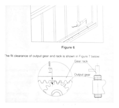
  • Manually move the gate (gate should be moved smoothly after motor unlocked) to check whether there is a fit clearance between rack and output gear, as shown in Figure 7.
  • Weld all the mounting screws to the gate firmly.
  • Make sure that all racks on the same straight line.
  • Pull the gate after installed, make sure the entire trip is flexible without any stuck.

Gear rack installation for Auto gate System

Warnings for Automatic sliding gate installation

  • To ensure safety, install safety stop blocks on both ends of the rail to prevent the gate from running out of the rail. Before installing the main engine, make sure that the safety stop blocks are in place and whether it has the function of preventing the gate from running out of the rail or safety range
  • Please make sure that the main engine and its components have good mechanical properties, and the gate can be operated flexibly when manually moved before installing the main engine.
  • Please note that for this product, one control can only drive one main engine, otherwise, the control system will be damaged.
  • Earth leakage circuit breaker must be installed in where the gate movement can be seen, and the minimum mounting height is to avoid being touched by children.
  • After installation, please check whether the mechanical property is good or not, whether gate movement after manual unlocking is flexible or not, whether the installation for infrared sensor (optional) is correct and effective.

Infrared Connection with Gate Motor

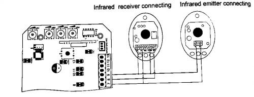
Infrared photocell function: In the closing process, when infrared ray of the photocell is covered by people or objects during its detection range, the gate will open immediately for security protection, The distance between photocell receiver and photocell emitter should be more than 2 meters, otherwise will affect the induction of the photocell If connect the infrared sensor, please remove the short connection between 8 and 9 on the 35 terminal.

Infrared Connection with Gate Motor